Autocad Lt For Mac Hatch Tool Palette
At the bottom of the window, you’ll see some information about the drive you have selected. Mac formatting tool for windows. Click the Erase tab if it’s not already selected.
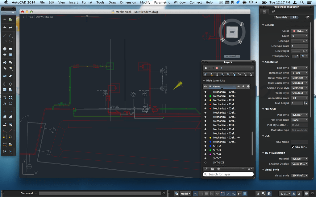
Gradient fill tools switch to hatch tools in AutoCAD LT. Raster image tools do not work in AutoCAD LT. Note If a tool palette file is set with a read-only attribute, a lock icon is displayed in a lower corner of the tool palette. Tool palettes are used to manage blocks, hatches, and other custom tools. If you see the palettes that are included with AutoCAD installation, you will see a collection of AutoCAD blocks, hatches, and other tools.
- Customizing the AutoCAD tool palette: A bit more context When you open Tool Palettes—accessed from the View ribbon tab or the TOOLPALETTES command (TP alias)—you’ll see several tabs. Each tab is a palette, itself with multiple tools.
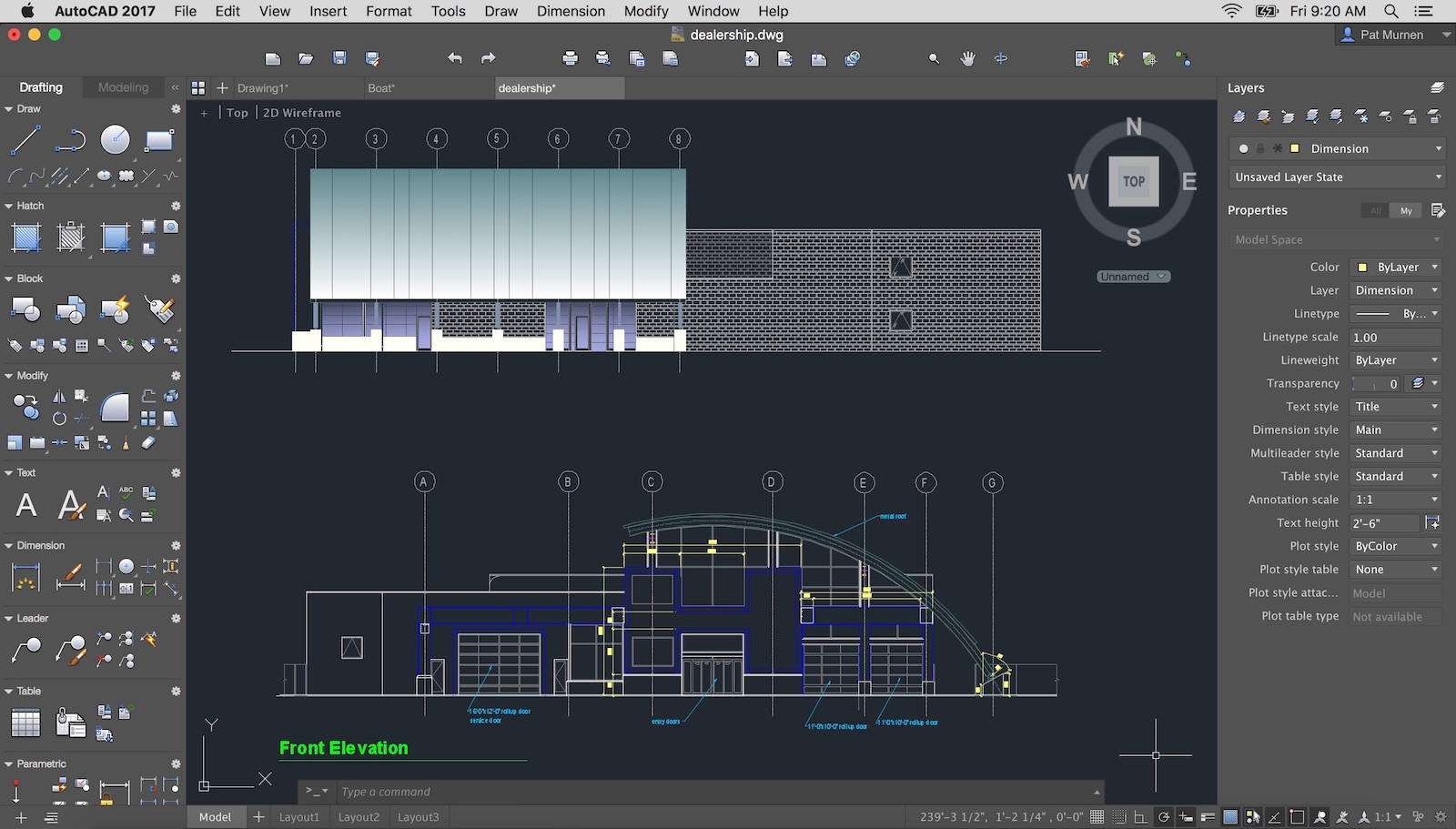
- Document your designs with the intuitive tools of Autodesk® AutoCAD LT® drafting software for PC and Mac. Produce precise 2D CAD drawings that you can easily edit, repurpose, and share.
Tool Palettes are one of the best CAD Management tools out there. If you’re looking to set symbol and layer standards, provide your staff with easy access to utilities, or put together a nice set of standard details then the tool palette is the place you want to start. The tool palette is a free-floating tab that you can bring up on screen and keep active while you work in your drawing, so you have quick access to common symbols, commands, and most any other tool you need to draft with. Think of it as a large, mobile, easily customizable toolbar and you won’t be wrong.
Autocad For Mac
Working With Tool Palette Groups
AutoCAD products come with a vast array of tools already loaded into your palette. They will vary, depending upon which vertical product you install, such as Civil 3D, AutoCAD Electrical or even just plain “vanilla” AutoCAD. You can turn the tool palette on/off using the toggle button on the Home tab of the ribbon panel or by typing TOOLPALETTES at the command line. The tool palette is divided into two categories: Groups and Palettes.

Groups: Groups are top-level folder structures that allow you to organize your tools into reasonably sized sections. In the example above, the standard AutoCAD palette has sections for Architectural, Civil, Structural, etc. symbols and tools so you can quickly access what you need. You can create your own Groups to organize company standards, use the ones that ship with your version of AutoCAD, or mix and match both together. We’ll explain how to customize your tool palettes later on in this tutorial.
Apple may provide or recommend responses as a possible solution based on the information provided; every potential issue may involve several factors not detailed in the conversations captured in an electronic forum and Apple can therefore provide no guarantee as to the efficacy of any proposed solutions on the community forums. Apple Footer • This site contains user submitted content, comments and opinions and is for informational purposes only. https://ninmgmt.netlify.app/cropping-tool-for-mac-book-pro.html.
Working With Tool Palettes
Palettes: Within each Group, you can create multiple palettes (tabs) that let you further sub-divide and structure your tools. In the above example, We are in the Civil Multiview Blocks Group (Civil 3D) and you can see that we have palettes for Highways, External Works, Landscape, and Building Footprints. This is a very convenient way of limiting the number of tools displayed to your users at any given time. You could put all the functions on a single palette of course, but having to scroll through several hundred functions to find the one you want sort of defeats the purpose. Remember, we want to increase productivity by helping users find what they need quicker. By breaking your tools down into organized palettes, the user can select the category they need and only have a small group of tools to choose from.

Using Tool Palettes
To use a tool from the palette you can simply click on it, or you can drag/drop it into your file. The nice thing about these tools is that as CAD Manager, you can set all the variables for using them right on the palette so that users don’t have to worry about settings, they can just click on the symbol or command and run it. You set these options by right-clicking on the tool and choosing the “properties” option. In the example above, we’ve set the Layer property for this symbol to C-ROAD-FEAT so that, regardless of what the current layer is when the user inserts this symbol into their drawing, it will always be placed on the C-ROAD-FEAT layer. As you can see, we have many other settings, such as color, line type, etc. that can be predefined to control how all the tools function, without having to depend on users to choose the correct settings.
Customizing Tool Palettes
The true power in tool palettes lies in the ability to customize them for your company standard symbols and commands. Customizing the palettes is pretty simple. To begin, right-click the grey title bar on the side of the palette and select the “Customize Palettes” option. This brings up a dialog box (above) that gives you areas for adding New Groups and Palettes. You create new Palettes on the left side of the screen by right-clicking and selecting “new palette”, and add new Groups in the same manner on the right side. You add Palettes to your Group simply by drag/drop from the left pane to the right pane.
Keep in mind that you can also “nest” Groups to create branching sub-options. We do this with our company standard details. At the top level, we have a group called “Details” which, when you hover over it, then displays options for “Landscaping” and “Drainage”. Each sub-group contains multiple palettes for items pertaining to that group, such as tree symbols, light symbols, etc.
Tool Palettes Autocad 2014
Adding Tools To The Palette
Once you’ve set your Groups and Palette structure, you’re ready to add the actual tools, commands, symbols, etc. that you want your users to access. To add symbols, you can drag/drop them from inside your open drawing or, if you’re working from a networked standards location, you can drag/drop the files you want right from Windows Explorer and release them onto your palette as shown in the example above. You can also add any custom commands or lisp files you’ve developed in a similar manner, just run the CUI command and drag/drop your commands from one dialog box to the other.
You can even drag and drop drawn items onto your palette. If you have a line drawn on a particular layer, with a particular line type that you want to be able to use regularly, you can just drag/drop that onto your palette and whenever you want to create a line of that type, just click on it and AutoCAD will run the line command with all the same parameters set for you. Think how easily you could draw tree lines or grid center lines on an architectural plan that way.
Sharing Your Palettes
To share your customized palettes with everyone in your CAD group, copy the folder containing the palettes out to a shared network location. You can find where your tool palettes are located by going to the TOOLS > OPTIONS function and looking at the “Tool Palette Files Location” path as shown above. Use the “Browse” button to change that path to the shared network location you want everyone to use. Lastly, you’ll want to find the “Profile.aws” file from you source system, such as: C:UsersYOUR NAMEApplication DataAutodeskC3D 2012enuSupportProfilesC3D_Imperial, which is where our Civil 3D profile is located, and copy it to the same location on every user’s machine.
There you have it: simple steps to creating a fully customize tool palette for your users! How are you working with tool palettes at your firm? Anything you want to add to this conversation?